|
The RS232 repeater
provides a expandable communication distance for standard RS232
interface. The expandable transmission distance for a RS232 repeater is
300 ft.
|
|
The
features of RS232 repeater are :
|
|

|
Standard EIA RS232
asynchronous communication protocol.
|
 |
Each repeater extends up to 300 ft communication distance. |
 |
Several repeater can be connected for a long distance
purpose. |
 |
AC power supported for 110V/220V selectable. |
 |
LED indicates when repeater is operating. |
 |
LED indicates when power is in normal mode.
|
|
|
The
package contains:
|

|
RS232 repeater. |
 |
AC power adapter. |
 |
User's manual. |
|
|
Hardware
configuration:
|
1. Block Diagram
|
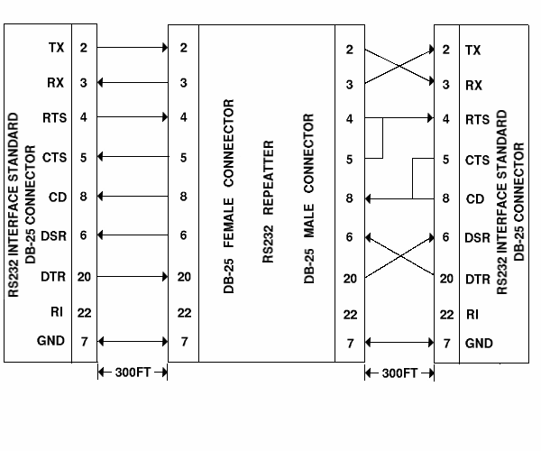
Observe the figure shown
in the following, the repeater contains three LED indicatiors, LED1
indicates power status, when LED1 is light means power is in normal
mode, LED2 indicates transmission data of RS232 signal and LED3
indicates transmission data of another RS232 signal.
|
|
2.
The signal assignment of a standard DB25 connector for RS232 is shown is
the following:
|
DB25 Pin#
|
Signal Name
|
RS-232C
Name
|
Direction
|
1
|
Chassis Ground (GND)
|
AA
|
Common
|
2
|
Transmit Data (TxD)
|
BA
|
Output
|
3
|
Receive Data (RxD)
|
BB
|
Input
|
4
|
Request to Send (RTS)
|
CA
|
Output
|
5
|
Clear to Send (CTS)
|
CB
|
Input
|
| 6 |
Data Set Ready (DSR)
|
CC
|
Input |
| 7 |
Signal Ground (SG) |
AB
|
Common |
| 8 |
Data Carrier Detect
(DCD)* |
CF
|
Input |
| 20 |
Data Terminal Ready (DTR) |
CD
|
Output |
22
|
Ring Indicator (RI)
|
CE |
Input
|
|
* Data Carrier Detect
(DCD) is also known as Received Line Signal Detector (RLSD).
|
|
3.
System Configuration
|
There are several
system configurations for different applications.
|
|
RS232
REPEATER BLOCK DIAGREM
|
 |
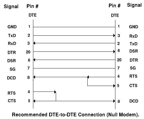
To connect your
converter to DATA TERMINAL EQUIPMENT (DTE), we suggest the following
connection.
|

|
