 |
| RS232 TO RS422/RS485 ISOLATOR
BOX |
|
|
|
| Product Code : ACONSMD/E(U) |
|
The RS232 to RS485/RS422
box provides bi-direction RS232 signals to RS485/RS422 signals
conversion features, which are used to expand long haul distance
communication for RS422 and multi-drop RS485 communication. The RS232
to RS485/RS422 box allows the input signals to be completely prevent up
to 5000Vrms, which offers customers a unique combination of protection,
speed, and versatility for industrial data communications applications.
There are 3 LED indicators correspond to Tx, Rx, and power signals.
|
|||||||||||||||||||||||||||||||||||||||||||||
| |
|||||||||||||||||||||||||||||||||||||||||||||
| The features of the RS232 to RS485/RS422
box are: |
|||||||||||||||||||||||||||||||||||||||||||||
|
|||||||||||||||||||||||||||||||||||||||||||||
| |
|||||||||||||||||||||||||||||||||||||||||||||
| Check that your RS232 to RS485/RS422 package includes the following items: | |||||||||||||||||||||||||||||||||||||||||||||
|
|||||||||||||||||||||||||||||||||||||||||||||
| |
|||||||||||||||||||||||||||||||||||||||||||||
| Hardware configuration: | |||||||||||||||||||||||||||||||||||||||||||||
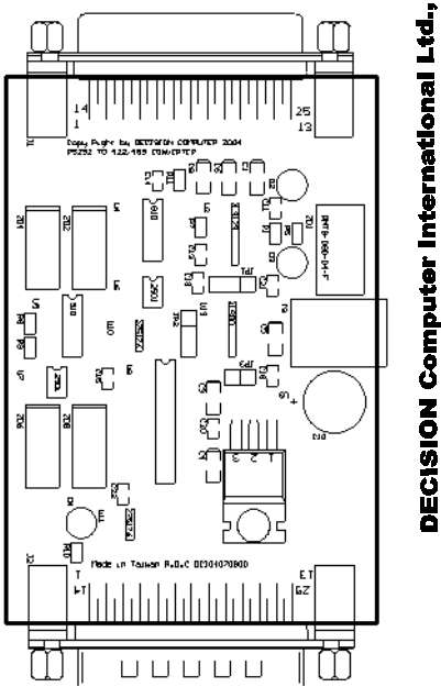
| The on boards
jumpers can be used to set RS422/RS485 mode and select delay transmit
time. |
|||||||||||||||||||||||||||||||||||||||||||||
|
JP1
(Jumper 1) Select delay transmit time. JP2
(Jumper 2) Select auto flow control. JP3
(Jumper 3) Select RS422 or RS485mode. |
|||||||||||||||||||||||||||||||||||||||||||||
  |
|||||||||||||||||||||||||||||||||||||||||||||
1. Select
RS422 or RS485 Mode The JP1 is used
to select RS422 or RS485 for port 2. To short pin means select RS485
mode.
2. Select Auto Flow Control  The JP2 is used to select auto flow control. To short 2,3 means auto flow control, user only need to send data from Tx signal, the hardware will control RTS signal automatically. To short 1,2 means select RTS flow control, while user need to send data, it needs to set RTS to 1, to enter driver mode, then send message or data. After sending message, it needs to set the signal to 0 to enter receive mode again. The auto flow control is work for RS485 mode.
3. Select Delay Transmit Time  The JP1 is used to select delay transmit time. To short the pin 1 and pin 2 means delay 4.6ms transmit time, and short the pin 2 and pin 3 means delay 40ms transmit time.
|
|||||||||||||||||||||||||||||||||||||||||||||
1. DB25 Female Connector for RS232
2. DB25 Male Connector for RS422
The applications of
RS232 to RS422 conversion are shown in the following:
a. Connect to RS422 Device  b. For Long Haul Distance Communication  3. DB25 Male Connector for RS485
The applications of RS232 to RS485 conversion are shown in the following: a. Connect to RS485 Device  b. For Long Haul Distance Communication  |
|||||||||||||||||||||||||||||||||||||||||||||
Information |